Receiver
The receiver in this project is the most vital part of the transceiver. The Receiver is build as a Superhet receiver.
table of content
- Graph of received signal
- Antenna Filtering
- Small signal Amplifier
- Mixers and Oscillator
- SSB Filter
- Demodulation
- Audio Amplifier
Graph of received signal
Inspiration from Land Boards
FunkY Receiver Path Diagram
This is a graph which shows the receiver path of the transceiver.
---
title: FunkY Receiver Path Diagram
---
graph TB;
Antenna -->|14MHz - 14.35MHz USB| 20m-Filter
20m-Filter --> TIA_NR1
TIA_NR1 -->|14MHz - 14.35MHz USB| IF@{shape: cross-circ, label: "IF Mixer"}
VFO -->|29.9952MHz - 30.3452MHz| IF
IF -->|15.9952MHz LSB| TIA_NR2
TIA_NR2 --> SSB-Filter["
    SSB-Filter
    2.7kHz BW"]
SSB-Filter --> TIA_NR3
TIA_NR3 -->|15.9952MHz LSB| AF@{shape: cross-circ, label:"AF Mixer"}
BFO -->|15.9979MHz| AF
AF -->|2.7kHz USB| Audio_Amp
Audio_Amp --> Speaker

    click Antenna "#antenna-filtering"
    click 20m-Filter "#antenna-filtering"
    click TIA_NR1 "#small-signal-amplifier"
    click IF "#mixers-and-oscillator"
    click TIA_NR2 "#small-signal-amplifier"
    click SSB-Filter "#ssb-filter"
    click TIA_NR3 "#small-signal-amplifier"
    click AF "#mixers-and-oscillator"
    click Audio_Amp "#audio-amplifier"
    click Speaker "#audio-amplifier"
Antenna Filtering
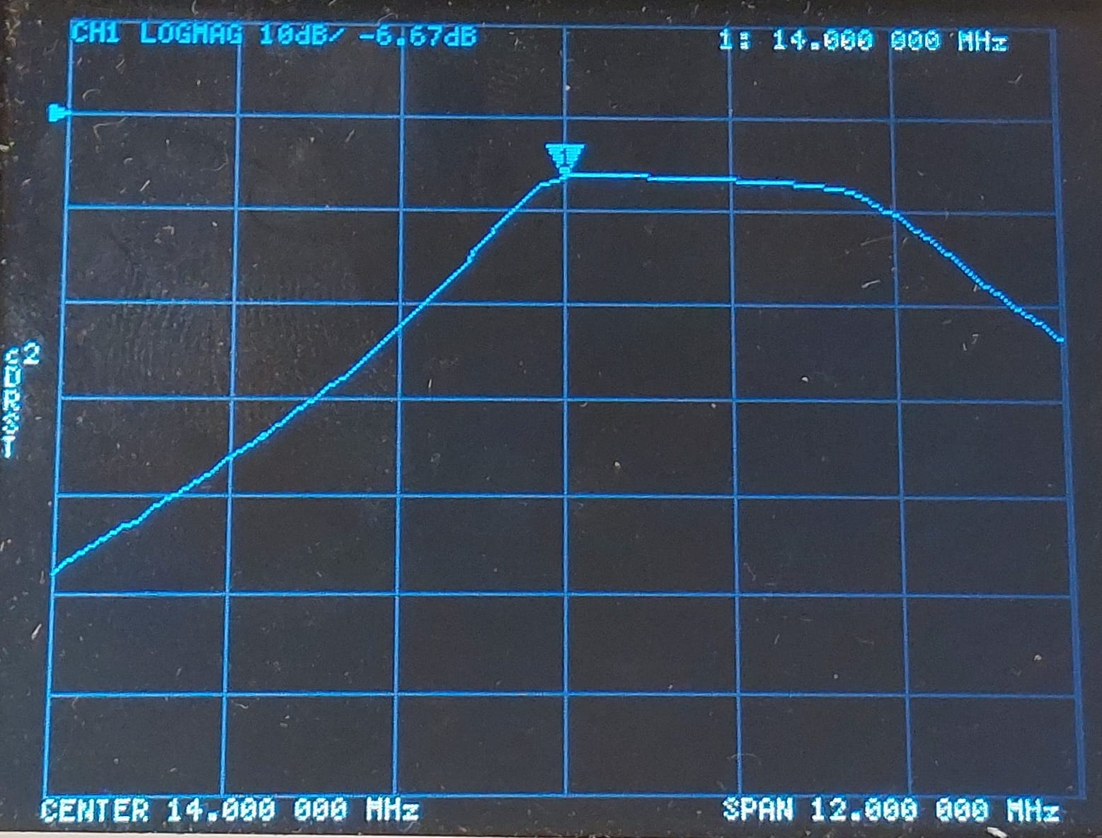
The antenna captures the electromagnetic waves carrying the radio signals. Since at the antenna there are signals from various frequencies present and we don’t want to get any problems with mirror Frequencies we have to filter out any unwanted frequencies.
Band-Pass Filters: The filters are used to limit the input signal to the target frequency band which in our case is the 20m Band ranging from 14MHz to 14.35MHz. These filters ensure that unwanted signals outside the ham radio’s operating range are rejected early in the process, minimizing interference and improving selectivity.
| Image Filter 20m | Lower Cutoff | Upper Cutoff |
|---|---|---|
.jpeg)
 |

 |
.jpeg)
 |
